SolarEdge SE3.5K - 33.3K inverters
Supported Devices
| Device Type | Modbus TCP (Ethernet) | RS485 | Curtailment | Minimum device firmware version |
|---|---|---|---|---|
| SolarEdge SE3.5K - SE33.3K | ✅ | ❌ | 🔶 (see warning below) | v3.0 (Tip: if the SolarEdge SetApp works, the firmware will be recent enough) |
CURTAILMENT IS ONLY SUPPORTED AFTER OBTAINING AN AGREEMENT WITH SOLAREDGE
If curtailment is not working on your SolarEdge device, it is probably not enabled by SolarEdge. Reach out to SolarEdge to enable control of your devices.
SolarEdge refuses to help customers with curtailment!
Wiring
For correct ethernet wiring: Follow the the guidelines for ethernet wiring.
MULTIPLE SOLAR EDGE DEVICES IN A CHAIN
Although it is theoretically possible to read out multiple SolarEdge linked via RS485 over Modbus TCP in a master-slave configuration, in practice this communication is NOT reliable.
You MUST connect each inverter individually via Modbus TCP!
Activating Modbus TCP communication
Via the SolarEdge SetApp (may require credentials)
- Connect the inverter to the same LAN network as the controller and make sure it is on.
- Download the SolarEdge SetApp: https://www.solaredge.com/nl/producten/software/setapp
- Open the SolarEdge SetApp and connect to the inverter. The app will help you do this.
- In the app, once connected to the inverter, go to the "Communication" -> "Modbus TCP" -> "Enable" menu and enable Modbus TCP.
- The Modbus TCP port is set to 1502 by default. Please leave it as is, and if it is set to another port, change it to port 1502. You can also use port 502 if necessary, but you will need to select the protocol for port 502 later when adding on the controller.
Via the inverter's Web interface via the inverter's WiFi access point (no credentials required)
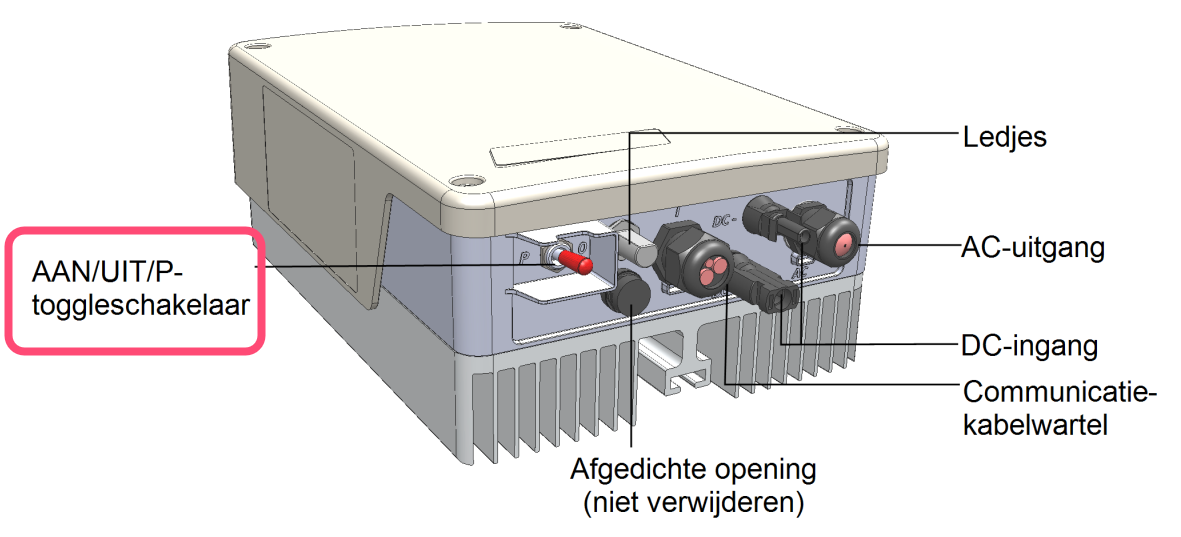
- Activate the inverter's WiFi access point by switching the red toggle switch at the bottom of the inverter to the "P" position for less than 5 seconds.
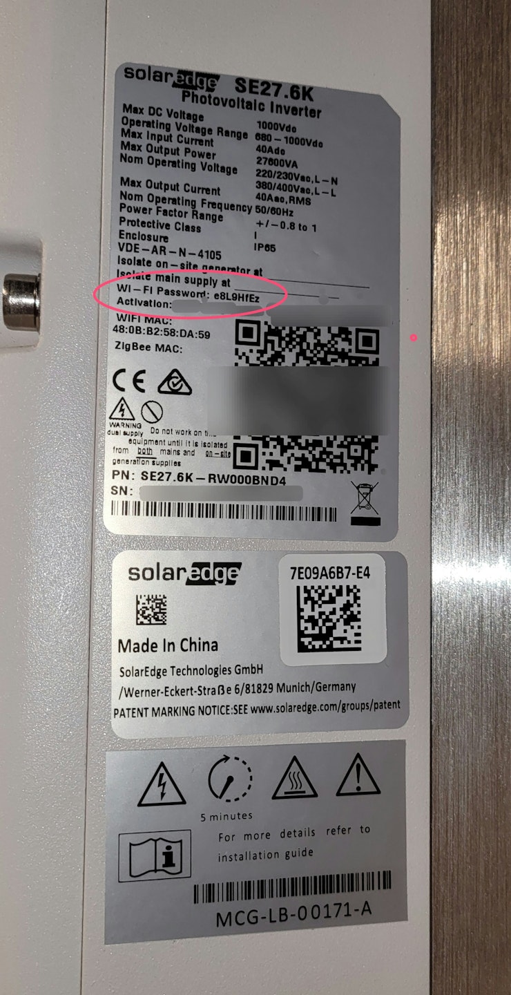
- Connect to the WiFi access point with a smartphone or computer. The WiFi password is on the label on the inverter
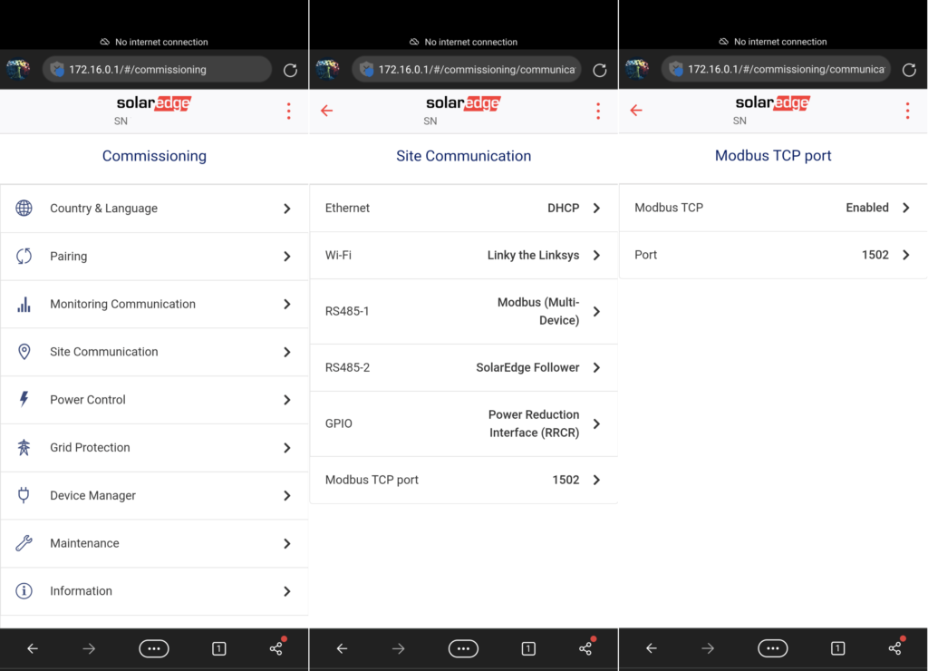
- In a Web browser, surf to http://172.16.0.1
- Go to "Site communication" -> "Modbus TCP port" -> "Modbus TCP" and set it to "Enabled".
- The Modbus TCP port is set to 1502 by default. Please leave it as is, and if it is set to another port, change it to port 1502. You can also use port 502 if necessary, but you will need to select the protocol for port 502 later when adding on the controller.